









Technical Reference
Full Documentation
Service Documentation
Need the technical details before scoping? This section explains what CAD drafting from scan data includes, what drawing types are available, how production works, and what to confirm before requesting a quote.
Have a project to scope? Tell us the site, the drawing types you need, and the measurement source.
Request a QuoteWe produce 2D CAD drawings from measured site data that architects, engineers, contractors, and facility teams can use as a measured reference for design coordination, project review, and existing-condition records.
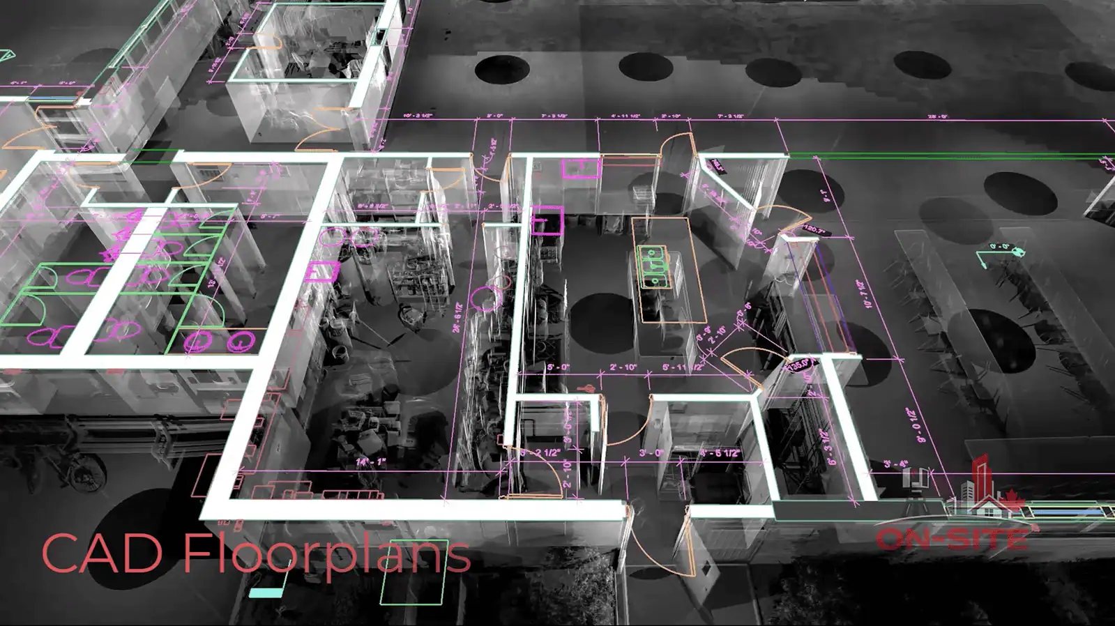
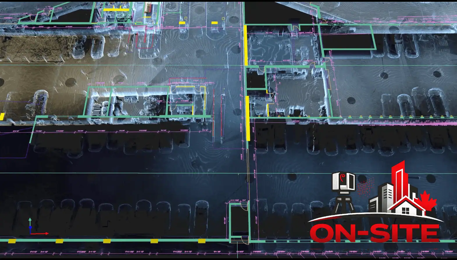
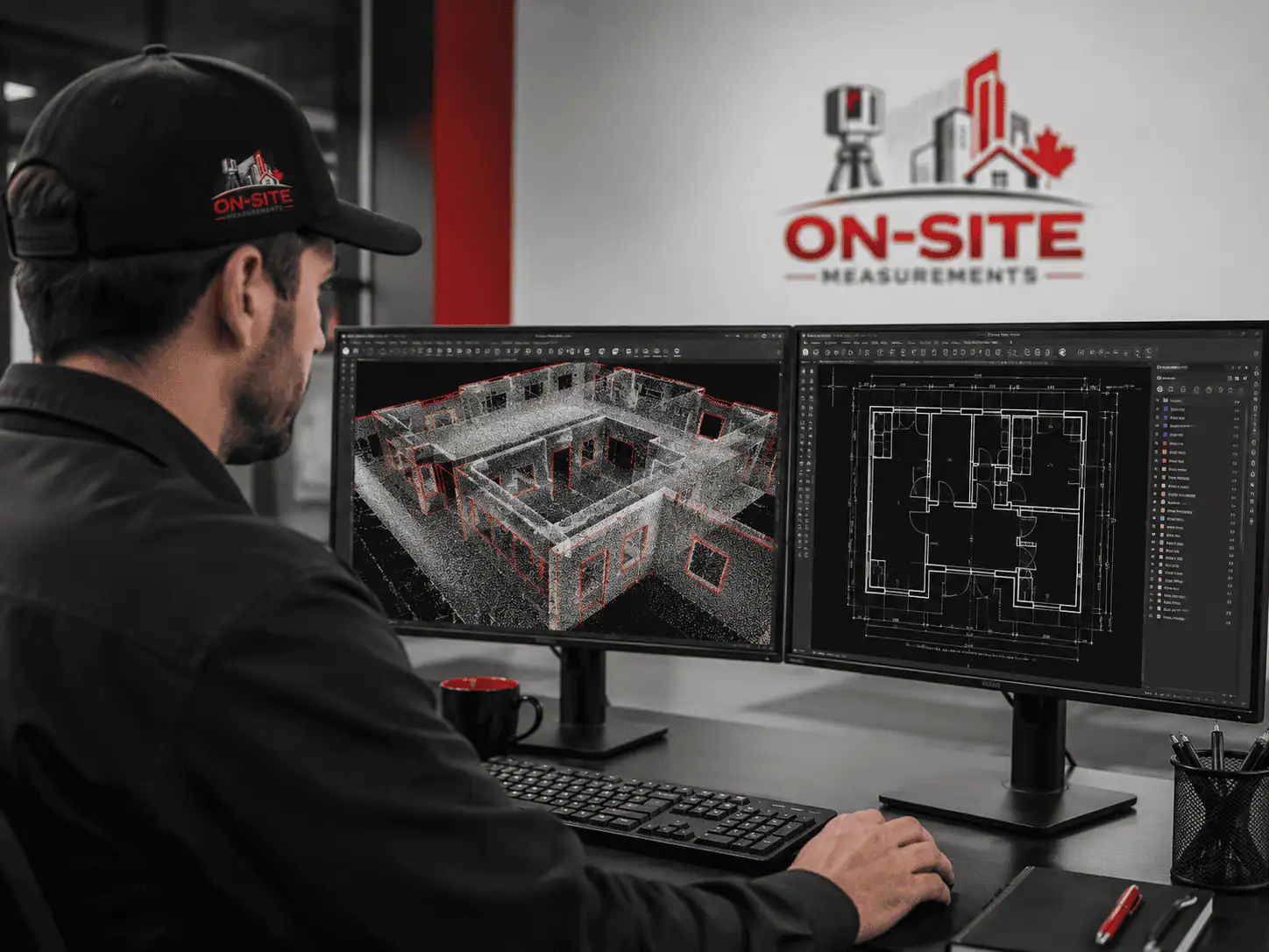
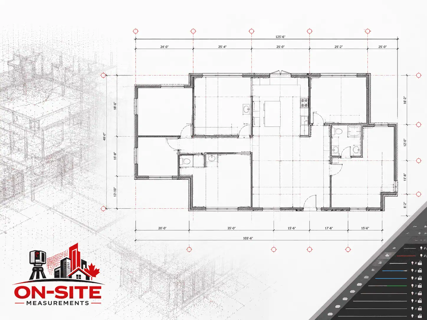
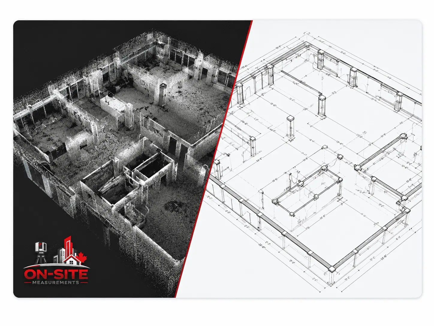
CAD drafting from scan data takes a registered point cloud as its dimensional reference and produces clean, dimensioned 2D drawings through a technician-driven process. The drawings are not automatically generated by the scanner. A drafter works from the measured data, building the agreed views at the agreed level of detail.
This page explains what the service includes, what drawing types are available, how the production process works, and what to confirm before a project starts.
What Our CAD Drafting Services Include
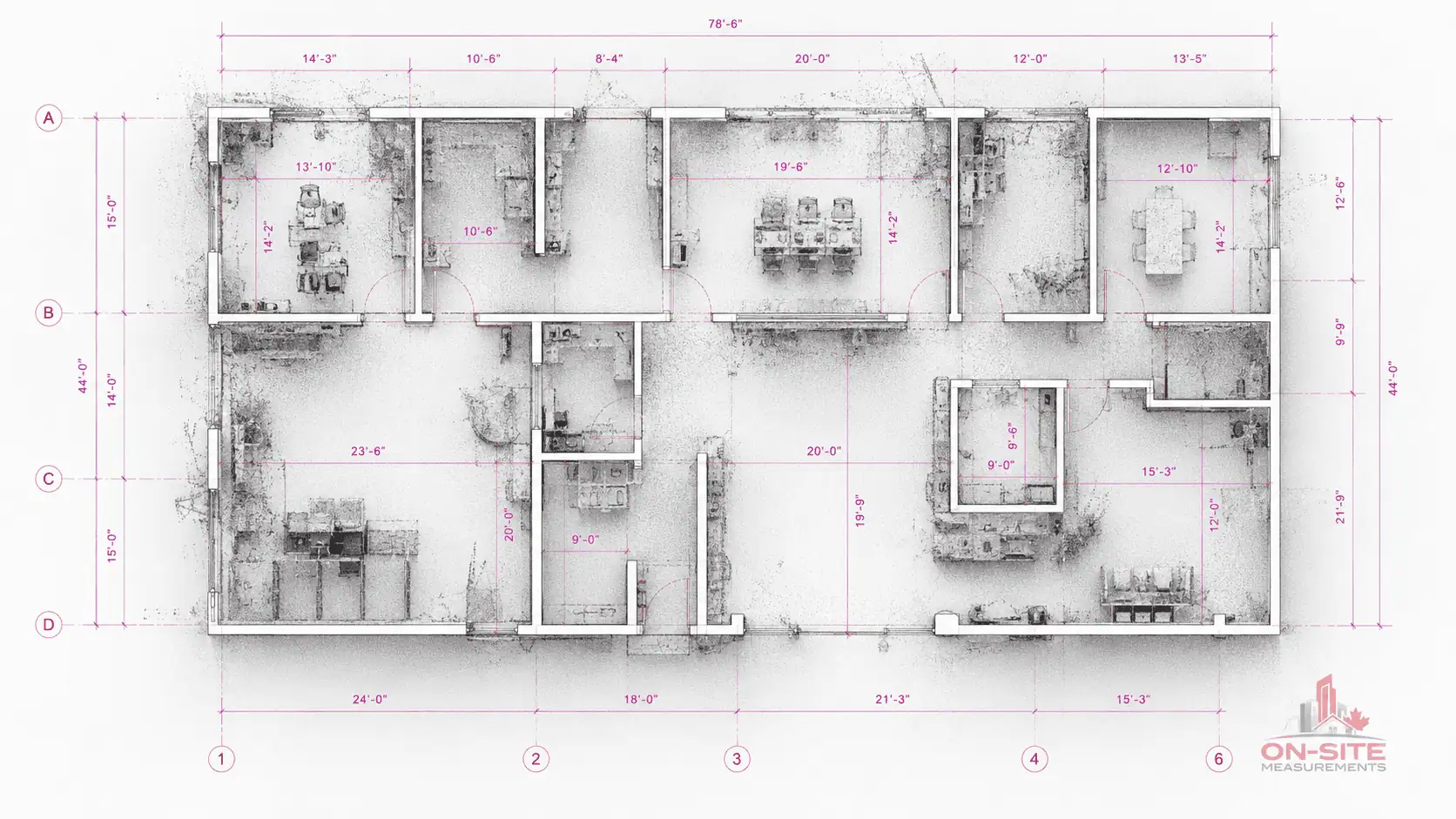
CAD drafting is the production of 2D drawings in DWG and PDF format from measured site data. The measurement source is most commonly a registered point cloud from 3D laser scanning. A technician uses that measured reference to draft the agreed drawing views at the agreed level of detail. The drawings are not automatically generated by the scanner, and the scope, drawing types, and level of detail must all be confirmed before drafting begins.
This workflow is also referred to as Scan to CAD, AutoCAD drawings from scan data, measured CAD plans, or 2D drafting from point cloud data, depending on the project context and how the team describes it. The term varies, but the production process is the same: measured site data is the reference; the drawings are the output of a deliberate drafting workflow.
CAD drafting produces 2D drawings in DWG and PDF. It is not a BIM modeling service and it is not a raw point cloud delivery. If your team needs a structured Revit or IFC model, see our Scan to BIM services. If your team needs the registered point cloud without a drafted layer, see our 3D laser scanning services. If your team needs a full existing-conditions documentation package, see our as-built drawing services.
What We Draft From
The measurement source determines what the drafting reference is. Confirming this before scoping prevents mismatches between what is expected and what can actually be drafted.
Laser scan data (Scan to CAD)
The most common input for CAD drafting at On-Site Measurements. A registered point cloud captured on site using 3D laser scanning becomes the dimensional reference from which the agreed drawing views are drafted. See our 3D laser scanning services for detail on how field capture and registration work.
Scan to CAD describes this workflow: scan data in, CAD drawings out. In this context, Scan to CAD refers to the scan-based input workflow under CAD Drafting, not a separate service.
Provided registered point cloud
Clients who already have a registered point cloud from a previous scan engagement can provide it as the drafting reference. When a client-provided point cloud is the input, we review it for coverage, data quality, and suitability for the agreed drawing scope before production begins. Coverage gaps in the provided data affect what can be drafted and will be flagged before drafting starts.
Existing drawings as a supporting reference
When old drawings, CAD files, or PDFs from a previous engagement are available, they can assist with scope planning and provide useful context during production. They are not a substitute for measured site data and should not be assumed accurate until the scan confirms them. On-Site Measurements does not offer PDF-to-CAD redrafting or sketch-to-CAD conversion as a standalone service. CAD drafting here is grounded in measured field data.
How CAD Drafting Works
1. Scope confirmation
Before any work begins, we agree on which areas are in scope, which drawing types are required, what level of detail is needed, what the measurement source will be, and what file formats and CAD version the team uses. Unclear scope at this stage is the most common source of missed elements and drawing revisions after delivery.
2. Input review or field capture planning
If the project includes on-site capture, we plan the scan to cover all areas required for the agreed drawing views. If the client is providing a registered point cloud, we review it for coverage and data quality before drafting begins. Any gaps that affect the agreed drawing scope are identified and discussed before production starts.
3. Field capture (when in scope)
The site is scanned using 3D laser scanning. Scanner positions are planned to support coverage of the agreed areas, subject to access, visibility, and line-of-sight conditions. See our 3D laser scanning services for detail on how field capture and registration work.
4. Data review
Scan positions are registered into a unified point cloud. Coverage checks are completed while on site when practical, and data quality is reviewed before drawing production begins. Areas outside the agreed scope or inaccessible during the field visit are noted at this stage.
5. Drafting
A technician drafts the agreed drawing views from the measured data at the agreed level of detail. Drafting involves real interpretation decisions: what to include within the scope, how to represent spatial conditions where scan coverage is partial, and how to handle site conditions that are ambiguous in the measured reference. These decisions are part of every drafting project.
6. QA review
Drawings are reviewed against the measured data for dimensional alignment and completeness within the agreed scope before delivery. This review checks drafted elements against the measured reference, not against old drawings or assumed conditions.
7. Handoff
DWG and PDF files are delivered in the agreed formats. DWG version and layer structure are confirmed during scoping. Delivery is confirmed before the project is closed.
Drawing Types and Scope Options
The views included in a CAD drafting project depend on the agreed scope. Not every project requires every drawing type.
Floor plans
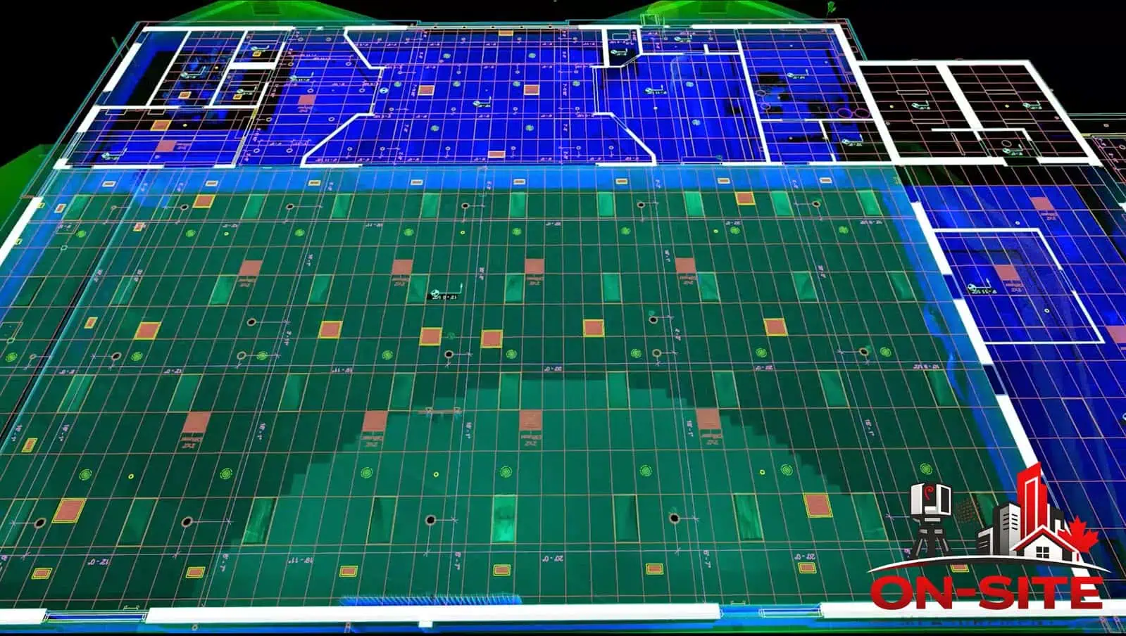
Horizontal sections showing room layout, walls, openings, columns, and spatial dimensions at an agreed cut height. Floor plans are the most common CAD drafting deliverable for renovation design, space planning, and existing-conditions documentation.
Reflected ceiling plans
Views of the ceiling plane showing structural elements, mechanical diffusers, lighting fixtures, and other ceiling-level elements when in scope. The level of MEP detail included depends on what is visible in the scan data and what the scope specifies.
Elevations
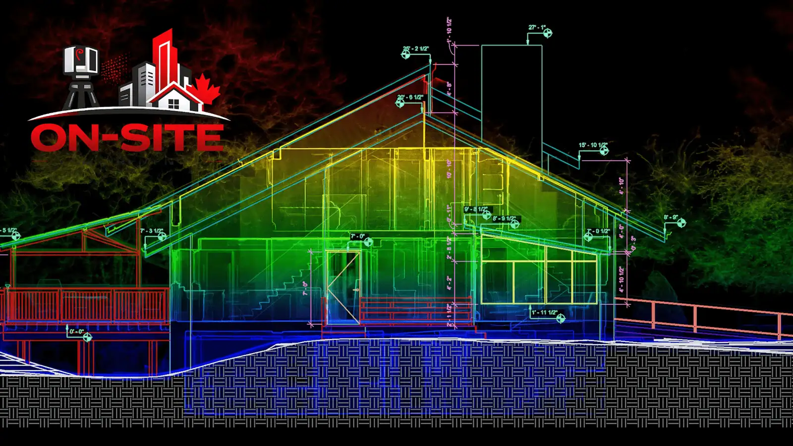
Vertical views of interior or exterior wall faces showing heights, openings, finishes, and spatial conditions. Scope specifies which faces are included and the required level of detail.
Sections
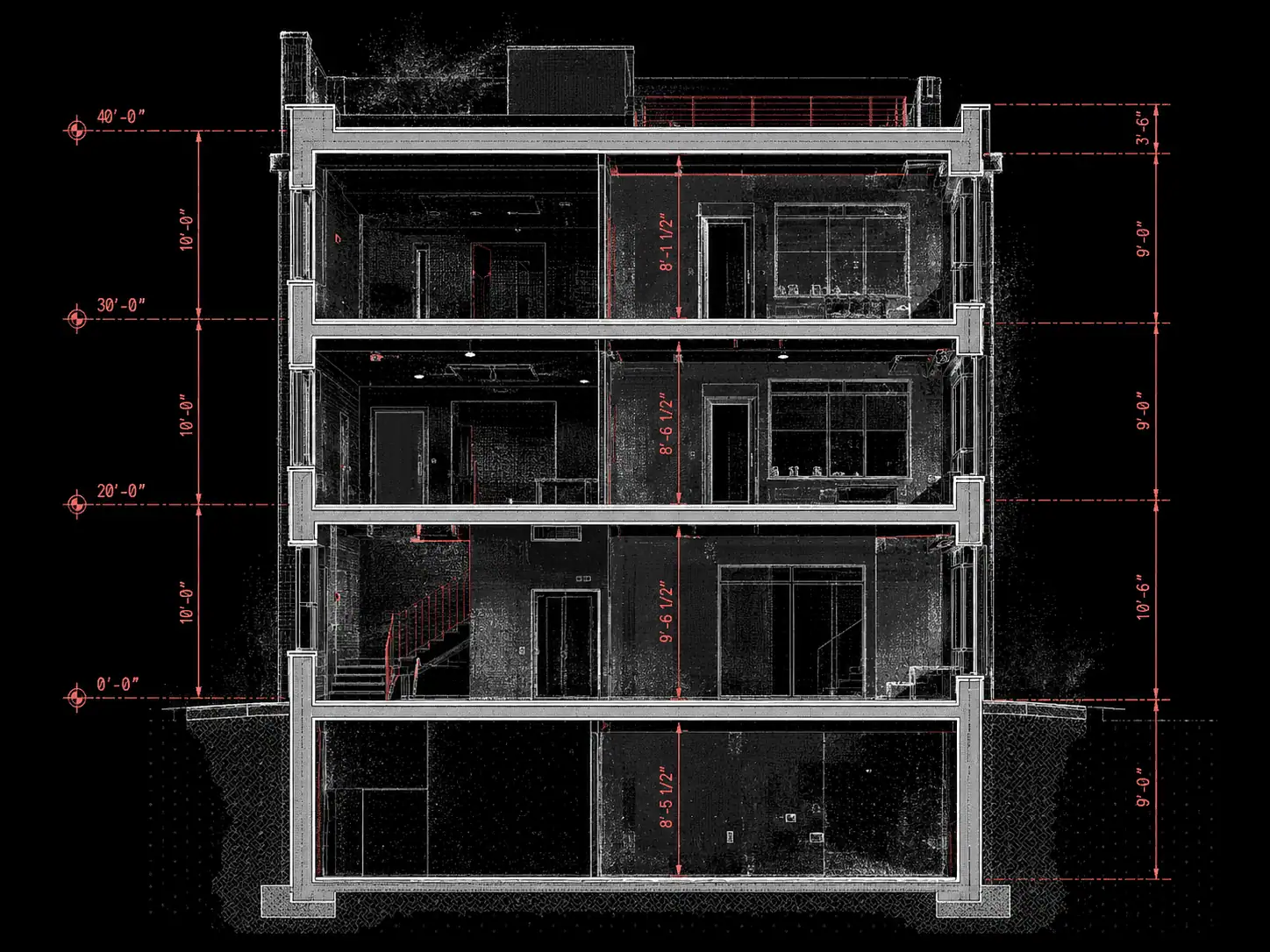
Vertical cuts through the space showing floor levels, slab edges where visible, exposed structural elements, and spatial relationships between levels. Scope specifies cut locations and what structural detail is required.
Exterior reference plans and roof plans
Plan views of captured exterior features or roof conditions when included in scope. These drawings do not document property boundaries, cadastral information, or legal survey data.
Space plans
Simplified plan views showing room layout and major spatial dimensions for lease documentation, tenant fit-out planning, or facility reference. Space plans are typically at a reduced level of detail compared to design-coordination-level drawings.
Detail drawings
Close-up views of specific conditions, connections, or elements when individual detail is part of the agreed scope. Elements included depend on what was visible and accessible during the field visit and what the agreed scope covers.
One important limitation across all drawing types: concealed structure, buried utilities, elements inside wall cavities, and inaccessible areas are not included by default. This should be discussed during scoping so that coverage gaps are understood before field work begins.
Deliverables, File Formats, and Handoff
The format delivered depends on what the downstream team will do with the drawings and which software they use.
DWG
The standard CAD format for measured 2D drawings. Prepared for the agreed CAD environment, commonly AutoCAD or compatible CAD platforms. DWG is the primary delivery format for CAD drafting projects. The CAD version should be confirmed during scoping if the team has a specific version requirement.
For review, sharing, and reference when the recipient does not need an editable file. PDF is typically delivered alongside DWG.
DXF
For compatibility with CAD platforms that do not use DWG as a native format. If DXF is required, confirm this during scoping.
Layer structure
DWG files are organized with a layer structure. If the team has a layer naming standard the drawings need to follow, specify this before production begins. Layer structure requirements add scoping detail that should be agreed before drafting starts.
If the project requires a Revit or IFC model rather than 2D CAD files, that is a Scan to BIM scope item. See our Scan to BIM services.
Other formats can be discussed during scoping if the downstream workflow requires something not listed here.
When CAD Drafting Is the Right Fit
Not every project requires the same deliverable. Understanding which output fits the project helps avoid scoping the wrong service.
CAD Drafting is usually the right fit when:
- The team uses AutoCAD or another CAD platform and needs DWG files they can use as a measured reference
- The project requires specific drawing types from scan data without a full existing-conditions documentation package
- The team already has a registered point cloud and needs CAD drafted from it
- The deliverable needs to be a 2D CAD file, not a structured 3D model
As-built drawings may be the better fit when:
- The project requires a complete existing-conditions documentation service including site capture and a comprehensive drawing set
- The team needs measured drawings covering multiple view types for renovation design, property documentation, or project handoff
- See our as-built drawing services for more detail on that workflow
Scan to BIM is the better fit when:
- The downstream team works in Revit and needs a structured model rather than 2D CAD files
- The project involves MEP coordination, clash detection, or an IFC handoff requirement
- See our Scan to BIM services for more detail on that workflow
A registered point cloud alone may be sufficient when:
- The team has BIM or CAD software and wants to work directly from the measured data without a drafted layer
- See our 3D laser scanning services for more detail
If you are unsure which deliverable fits your project, a scope conversation before committing to a package can help clarify the right output.
Industries and Common Project Types
CAD drafting from scan data is used across a range of project types where 2D CAD deliverables support design, coordination, or facility management.
Architecture and interior design
Architects and interior designers use measured CAD drawings as the starting point for renovation design, tenant improvement planning, and building additions. Working from a measured DWG base file, rather than from old drawings or manual measurements, helps reduce the risk of design decisions based on records that no longer match site conditions.
Commercial real estate and property management
Space plans, area calculations, and measured floor plans support lease documentation, asset records, and tenant fit-out planning. Measured CAD documentation is often needed when taking over a space, preparing for a new tenancy, or updating building records.
General contracting and construction management
Contractors use existing-conditions CAD drawings to plan demolition scope, coordinate subcontractor work, and review measured visible conditions before a renovation begins. Measured plans from scan data help reduce the risk of decisions based on outdated or incomplete records.
Structural and MEP engineering
Dimensioned CAD views of existing structure, mechanical equipment, and ceiling spaces give engineering teams a measured reference for retrofit planning. CAD drawings from scan data reflect visible, measurable conditions at the time of the survey.
Facility and property management
Floor plan records, space summaries, and area documentation support maintenance planning, capital budgeting, and equipment replacement for managed facilities. Measured CAD plans provide a measured spatial reference based on the agreed scope for facility teams.
Heritage and complex buildings
Irregular geometry, thick masonry walls, and non-standard spatial conditions make heritage buildings well suited to scan-derived CAD documentation, where hand measurement is impractical or unreliable.
Industrial facilities
Plant floor layouts, equipment positions, and spatial records can be produced in CAD from scan data to support retrofit planning, equipment replacement, and facility management. Industrial CAD drafting projects typically require careful scope definition around which elements are drafted and at what level of detail.
Scope Assumptions, Accuracy, and Limitations
CAD drawings produced from measured site data document visible, measurable existing conditions based on the agreed scope. Understanding what falls outside that scope matters as much as knowing what is included.
What drawings can show
Visible surfaces, elements, and spatial relationships that were accessible and within the agreed scope during the field visit. This includes walls, openings, floors, ceilings, exposed structure, and visible MEP elements when in scope.
What drawings cannot show by default
Concealed structure, buried utilities, elements inside closed wall cavities, and any area that was not accessible during the field visit are not included in CAD drawings. If specific concealed elements are critical to the project, alternate verification methods should be discussed before the scope is confirmed.
Accuracy and the measurement source
The dimensional reliability of CAD drawings depends on the quality and coverage of the measured input data, the scanner and workflow used during field capture, site conditions, and the agreed level of detail. We do not state a specific accuracy tolerance because requirements vary by project. If your project has specific accuracy requirements, those should be discussed during scope confirmation so the field plan and drafting scope can be planned around them where feasible.
Drawings are drafted by a technician
CAD drawings are drafted from measured data by a technician. They are not automatically generated by the scanner or by CAD software. Drafting involves interpretation: what to include within the agreed scope, how to represent conditions that are partially visible or ambiguous in the measured reference, and how to handle areas where coverage was limited.
On-Site Measurements does not provide
Engineering sign-off, architectural stamping, permit consulting, code compliance review, or legal land survey services. CAD drawings document visible existing conditions from measured data. How drawings are used in any downstream design, engineering, permit, or regulatory process is the responsibility of the team using them.
What to Share Before Requesting a Quote
To give you an accurate scope and timeline, it helps to have the following before we talk:
- Site location: City and province
- Project type: Renovation, tenant improvement, facility documentation, commercial real estate, heritage, industrial, or other
- Measurement source: Will On-Site Measurements scan the site, or will you provide a registered point cloud
- Drawing types needed: Floor plans, reflected ceiling plans, elevations, sections, exterior reference plans, space plans, detail drawings, or a combination
- Level of detail: Space plan level, coordination level, or another agreed standard
- File formats: DWG, PDF, DXF, or a combination
- CAD version: Which version of AutoCAD or other CAD platform the team uses
- Areas to draft: Specific rooms, floors, the full building, or a defined zone
- Project deadline: When drawings need to be delivered and whether there are phased milestones
- Access restrictions: Occupied, active, or restricted areas, required working hours, or safety requirements
- Existing documentation: Old drawings, CAD files, or previous survey data useful for scope planning and reference
You do not need to have every answer before reaching out. If anything is unclear, we can work through it together during the scoping conversation.
Frequently Asked
Common CAD Drafting Questions
What is CAD drafting?
CAD drafting is the production of 2D drawings in CAD format from measured site data. At On-Site Measurements, the measurement source is most commonly a registered point cloud from 3D laser scanning. A technician uses that measured reference to draft the agreed drawing views at the agreed level of detail. The drawings are not automatically generated by the scanner. CAD drafting requires scope definition, production decisions, and review against the measured data before delivery. This workflow is also referred to as Scan to CAD, AutoCAD drawings, 2D drafting from point cloud data, or measured CAD plans, depending on the project context.
What is Scan to CAD?
Scan to CAD is the workflow where a registered point cloud from 3D laser scanning is used as the dimensional reference to draft 2D CAD drawings. It is not a separate service. It is the scan-based input workflow under CAD Drafting. The scan data comes in as the measured reference; the CAD drawings go out as the deliverable. A technician does the drafting. The scanner does not produce CAD files automatically.
What is the difference between CAD drafting and as-built drawings?
Both services produce 2D drawings of existing conditions. The distinction is in scope and framing. As-built drawings refers to the full existing-conditions documentation service: scan, draft, and deliver a measured drawing set as a complete package. CAD Drafting refers to the drafting production layer: producing CAD-format files from scan data or a provided point cloud. In practice, some projects fit naturally under one service or the other based on how the team describes what they need. If you are unsure which framing fits your project, a scope conversation can help clarify it. See our as-built drawing services for more detail on that workflow.
What drawing types are available from CAD drafting?
Common options include floor plans, reflected ceiling plans, elevations, sections, exterior reference plans, roof plans, space plans, and detail drawings. Not every project requires every drawing type. The scope is confirmed before any field work begins so the scan coverage plan and drafting brief are aligned with what the project actually needs.
What file formats are delivered for CAD drafting?
DWG and PDF are the standard delivery formats. DWG is prepared for the agreed CAD environment, commonly AutoCAD or compatible CAD platforms. PDF is provided for review and reference. DXF is available when required for compatibility with other CAD platforms. The CAD version and any layer structure requirements should be confirmed during scoping. If a Revit or IFC model is needed rather than 2D CAD files, that is a Scan to BIM scope item.
How accurate are CAD drawings produced from scan data?
The dimensional reliability of CAD drawings depends on the quality and coverage of the measured input data, the scanner and workflow used during field capture, site conditions, and the agreed level of detail. We do not state a specific accuracy tolerance because requirements vary by project. If your project has specific accuracy requirements, those should be discussed during scope confirmation so the field plan and drafting scope can be planned around them where feasible.
What affects the cost of CAD drafting?
Several factors influence project cost: Site size: Larger or multi-floor spaces require more field time and more drafting time Drawing types and quantity: A full package with multiple view types requires more production time than a floor-plan-only scope Level of detail: Higher detail levels require more careful field coverage and more time in drafting Measurement source: Whether field capture is included or a point cloud is provided by the client affects the overall scope Access constraints: Occupied spaces, after-hours requirements, or restricted areas affect both the field plan and the timeline Layer structure or CAD version requirements: Custom layer naming or specific version requirements add scoping detail Mobilization: Site location, travel, and access scheduling affect the total project cost We do not publish standard pricing because project conditions vary too much to make a price list useful. Contact us with your project details and we will discuss what the scope realistically involves.
Have a project in mind?
Send us the site, scope, and deliverables you need.
We will help confirm the right capture method before work begins.
Industries That Use This Service
- CAD drafting support for architects and design teamsCAD backgrounds and measured plans as design inputs.
- CAD deliverables for engineering workflows2D CAD drawings of existing conditions for engineering reference.
- CAD drawings for facility recordsUpdated CAD floor plans and building records for facility teams.
- CAD plans for industrial facility documentationEquipment layout and mechanical room drawings from scan data.
This Service in Specific Cities
City-specific pages with local project context, use cases, and quote guidance.
- CAD Drafting in TorontoCAD drafting for Toronto and GTA renovation, tenant improvement, and commercial facility projects.
- CAD Drafting in VancouverCAD drafting for Vancouver and Lower Mainland renovation, tenant improvement, and heritage building documentation projects.
- CAD Drafting in CalgaryCAD drafting for Calgary commercial renovation, tenant improvement, industrial facility records, and property management projects.