Technical Reference
Full Documentation
Service Documentation
Need the detail before scoping? This section explains what verification includes, who orders it and when, what to confirm before the site visit, and what the report does not decide.
Have built work to check? Tell us the stage, the model revision and the elements in scope.
Request a QuoteWe scan what was built, align it to what was designed, and report where the two differ. The deliverable is a deviation analysis that tells the project team which elements sit outside the agreed limits, before finishes conceal the work.
As-built verification is not the same as as-built documentation. Documentation records an existing building where no reliable record exists. Verification starts from a design model that already exists and answers one question about the building in front of you: does the built work match it, and where does it not?
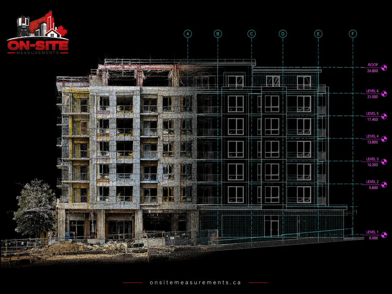
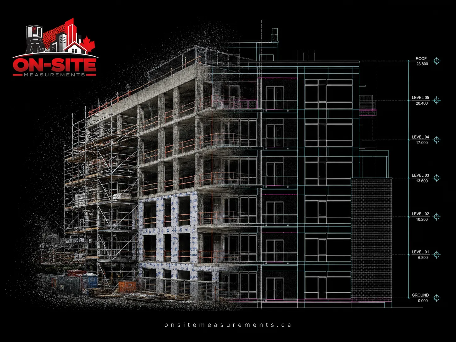
Verification uses a registered point cloud as the measuring instrument and the design model as the reference. A technician aligns the two, compares the agreed elements, and produces a report that a construction or design team can act on.
Scan of the constructed work
The agreed elements are captured on site with 3D laser scanning at the stage that matters, most often after structural work is complete and before mechanical, electrical and plumbing rough-in closes the space. Timing is part of the scope conversation: work that is already concealed cannot be verified.
Alignment to the design model
The point cloud is aligned to the design model in the project coordinate system, using the control, gridlines or survey reference the project already relies on. The design model revision used for comparison is recorded in the report so there is no ambiguity about what the built work was checked against.
Deviation analysis
Each element in scope is compared to its modelled position. Differences are reported as a colour-mapped comparison plus annotated plans and sections that show where the built work departs from the model and by how much, against the limits the project team sets. The report states the difference. Whether that difference is acceptable is a decision for the design or engineering professional responsible for the element.
Record drawings at substantial completion
Where the project needs an as-constructed record rather than a comparison, the same scan is drafted into record drawings in DWG and PDF, following the same approach as our as-built drawing services. Both outputs can come from one site visit when they are scoped together.
Related services and reading
If the project has no design model and needs an existing-condition model built from scratch, see Scan to BIM. For the workflow in detail, read as-built verification and deviation analysis. A worked example is the construction verification scanning project in Toronto. City detail for scanning: Toronto, Vancouver and Calgary.
General contractors and construction managers verify structural work before trades install against it, so the coordination model reflects the slab edges, columns and cores as they were actually poured.
BIM managers and VDC teams check that the built condition matches the coordinated model before the next trade's fabrication is released.
Owners and consultants use verification at substantial completion to confirm what was delivered, and to produce a record set that matches the building rather than the last design revision.
Fabricators and specialty trades verify openings, embeds and connection points before shop drawings are finalised for elements that must fit first time.
Deliverable scope is confirmed before the engagement starts.
- Deviation report (PDF): colour-mapped comparison of scan against model, annotated plans and sections, and a summary of elements outside the agreed limits, with the model revision and control reference recorded.
- Registered point cloud (E57, RCP/RCS): the scan data used for the comparison, delivered when in scope so the team can check anything the report does not cover.
- Record drawings (DWG, PDF): as-constructed plans, sections and elevations drafted from the scan when a record set is part of scope.
- Updated model elements (RVT): agreed elements adjusted to the as-built position when the project wants the coordination model to reflect the built condition.
The design model and its revision
Verification needs a design model or drawing set to compare against, in a format that can be aligned to scan data, most commonly Revit or IFC. Confirm which revision represents the intent the built work should be checked against.
Coordinate system and control
The scan is aligned to the project's coordinate system using the control or gridlines the project already uses. Where no control exists, the alignment method is agreed before the site visit and recorded in the report.
Elements in scope and agreed limits
Verification is scoped by element: slabs, columns, cores, openings, embeds, steel, ductwork, or whatever the project needs checked. The limits used to flag a deviation come from the project team and its specifications, not from us.
Construction stage and access
Only visible work can be verified. Rough-in is the usual window for structure and services. Areas that are closed, occupied or inaccessible at the time of the visit are outside the report, and are noted as such.
Frequently Asked
Common As-Built Verification Questions
As-built verification compares a laser scan of the constructed work against the design model and reports where the two differ. The scan is the measuring instrument, the model is the reference, and the deviation analysis is the deliverable. It is ordered when a project team needs to know whether built work matches the coordinated design before the next stage proceeds.
Documentation records an existing building where no reliable drawings exist, and the output becomes the reference. Verification requires a design model that already exists, and the output is the difference between that model and the built condition. A project can need both, at different stages, as separate scopes.
Clash detection runs inside the model and finds conflicts between designed elements before anything is built. Deviation analysis runs against reality and finds differences between what was designed and what was constructed. One is predictive; the other is a check after the fact.
At the stage where the elements in question are complete but still visible. For structure that usually means after concrete or steel is finished and before mechanical, electrical and plumbing rough-in. For a record set, substantial completion. Work that has been concealed cannot be verified afterwards.
The design model or drawing set with its revision, the coordinate system or control the project uses, the list of elements to check, the deviation limits the project applies, and the construction stage and site access details.
No. The report states what the difference is and where. Whether it matters is a decision for the design or engineering professional responsible for the element. We provide the measurement, not the judgement.
Yes, when it is included in scope, and we generally recommend it. The report answers the question that was asked; the point cloud retains everything that was visible, which is what teams return to when a different question comes up later.
The number and type of elements in scope, the size of the area, the construction stage and access, whether record drawings or model updates are included, and whether the project already has usable control. Scope is confirmed before quoting.
Have a project in mind?
Send us the site, scope, and deliverables you need.
We will help confirm the right capture method before work begins.